Friday, December 26, 2008

Master caution button project

Here below you can see a picture of the master caution button project.

The green box is the bigger squared pipe. The litle pipe, inside the green box, is represented by a black box.
The big green box moves up and down around the blue supports (there are 2 holes in the big pipe and the supports, screwed in the little pipe, will pass through such holes).
Two springs kee the button in the upper position. When the user presses the button, a switch is closed activating a line in the SIOC software.

The blue supports in the upper side are screwd to the panel and fix the button in the right position. The other 4 supports, at the bottom of the 2 pipes are needed to blck the switch and the screws. You can imagine a hole in a pipe whenever a support is fixed in the other squared pipe.

Plexi has to be fixed very carefully because it needs to support user pressures that could be quite strong. The plexi will have a written but the caution/warning message will be distinguished by the color of the leds (yellow for warning and red for alert).

The picture has no sizes but if someone is interested I could write down a better project with measures. However, the little squared pipe is 7cm long and the biggest is 6cm. I have bought such pipes in a workshop for around 3EUR each.

At the present I have cutted the two pipes and made the holes in the biggest one. The holse still needs to be refined. and I ma still thinking which is the best way to do that.

The design is quite clear for me. But there are a lt of techinical issues that i don´t know yet how to address. For example how to fix the springs and the switch. And even which type of switch to mount.
Another point is the plexi that should have the same level of the surface of the pipe but fixed somehow to allow the user to press it without bracking or moving.
Finally, until the whole button will be ready I don´t know if the bissgets pipe will move smoothly enough inside the little one.

As usual, I will post some picture in the blog.

Master caution button design

After browsing the web I have found that master caution buttons ready to use are quite expansive (something like 50EUR or more). I found that price so unbeliavable for a single button that Ideide to try to build one from scratch.

I bought two squared pipes with a very similar size in such a way the biggest one surround the little one leaving a very little space. I will put the leds into the little one while the bigger one moves forward and backward. When in backward position it will press a switch in order to clear the warning.

I kno that what I said is not clear enough. If I have enough time I will draw the project and put here an image.
I still have some concern about this idea but I found it a very interesting challenge.

That´s it for now. Merry Christmas and happy new year to everybody!

Thursday, November 20, 2008

Cockpit light

If you fly by night you know that it is very dificult to see the landscape outside of the windows. You can trick the monitor but the result is always bad looking. To enhance the situation you can think of turning off all the light and fly in a dark room. This strategy works of course but it is very difficult to find the keys of the keyboard or, even worst, you can't write down notes while flying online. Well, I don't know you but I have to write down al least metars, radio frequencies and take off clearances.
I agree that the problem of the lighting is temporary because when all the controls will be implemented at hardware it will not be needed anymore to find the keys of the keyboard. But what until then?
I thought about this problem for a long time and arrived to the following conclusion. I need a light that can be turned on and off independently of the simulator and maybe later on integrated with the 767 light switch. The light should be strong enough to allow writing notes and reading the keyboard but not too strong to reduce the visibility of landscape details flying by night.
I bought a couple of blue led strips and positioned in the upper right and left side of the closet. They are turned on and off by an apposite switch positioned below the table.
The following picture shows the environment while flying:
You might easily find it kitsch but for me the final effect is quite good: no artificial light reflected in the two screens, lightning is soft and relaxing but strong enough to read the keyboard or write down notes.
A possible next step could be that of integrating the lighting to the 767 cockpit. The two 24 leds strips needs 12V power that I already have in the power supply. The SIOC software already catch the events of the cabin light switch but up to now it only sends the command to the simulator. It would be possible to close a 5V output line that in turn powers on the leds with the help of a raleigh or something like that. It is something I will think about...
Last but not least the price. I payed the two strips of 24 blueleds, a 12V dedicated power supply, cables and the switch around 50 EUR. Half an afternon was the time to mount the hardware in the closet.

Thursday, November 13, 2008

New radio and MCP panel

The refactoring the radio and MCP panelsis finally completed. You can see a snapshot of the previous situation in this post. The radios were in the left side in two white wodden frames. The MCP and the EFIS were below the two monitors in a very big wodden box bought from Ikea a lot of time ago.
The idea was to have a new box with the EFIS and the MCP in the upper side and the radios at the bottom.The new panel is shown by the following picture.
As you can see the new panel is much more compact. The little screwed panel in the upper left side is intended to contain some buttons controlled via opencockpit. That panel is not as wide as I hoped so I think I will put there not more then 4 buttons. For sure it will contain the master switch and the toga.
Just behind the webcam there is the power switch and another switch to close the contacts of the dip switches of the CPFlight MCP for upgrading the firmware.
The wood is painted with a water paint and the color is RAL7043. The new CPFlight radios have almost the same color of the panel while the old ones, the MCP and the EFIS, are quite different. However the final result is not bad and for sure much better then the original situation.
Yesterday night I made my first flight with the new panel, from EHAM to LIMC. I took this photo while climbing to final FL310 under Brussel CTR:
You can see the panel back lighted. In the left screen the VC and in the rigth monitor IVAP, the FMC and the radio panel. Most of the time, I use the left monitor to browse the charts.
Just upon the rigth screen you can see the three leds of the cabin light, the read and white beacons from the opencockpits light panel.

Monday, October 27, 2008

Work in progress with MCP and radios

Last weekend I began the building of the new panel with MCP, EFIS and radios I bought from CPFlight.
The panel is composed of a box of 64x17 cm to be positioned below the left monitor. In the upper side of the box there will be the EFIS then the MCP. At the bottom, from left to righ, XPNDR, COM, ADF VOR. 
At the present the scheleton of box is completed and the elictrical components are in place. There will be one button for turning ON/OFF the electronics and a two poles switch button for upgarding the firmaware without insering the 2 dip switches in the rear side of the MCP by hand. In this way the firmaware can be upgraded without moving the panel.
At the right upper side of the front panel there is less space then I initially supposed: only  a 8x6 cm little panel. I will put there the master switch, the GA and the button to switch between auto and manual setting of the VOR for the capitain.
In the first step this panel will be empty but ready for the replacement with the panel with the buttons.
For the GA button I have found at conrad a little squared button that can be reasonably used. It has no led on board and so it can't be back lighted. 
The master switch is the most complex button because it has more then one led, at least a red and a yellow one for caution and warning. Till now I have found no button like that on the market. Of course it is sold by specialised web sites but it is very expansive.
The button to switch between manual and automatic VOR tuning can be one of the button (with a green led) I have already used for the light panel.
I am currently investigating the way to build the master switch and korry buttons. I subscribed to mycockpit forum and ther I have found some interesting solution. I will create a new post later with some good solution.

Tuesday, October 21, 2008

Refactoring of the MCP/EFIS/RADIOS panels

It seems that next week I have to put all my stuff out of the shelf :(

I'll take the chance to fix the not working button of the light panel. At the same time I want to change the setup of the MCP, EFIS and radios. Current setup was in fact a temporary solution that is in place for more then one year. 

The idea is to create a wodden frame having the MCP and the EFIS in the upper side and the 4 radio modules at the bottom. If I have enought space, I will insert some controls in the upper side of the panel. I am thinking of the master switch and GA button or the annunciators or something else. The new panel, painted in RAL 7043, will be placed below the 2 monitors, where the MCP and EFIS are at the present. Giving that I already have at home all the wood I need, i guess that this remake will last for some days only. 

At the end, I will have the left side free for new panels and space on the left for e new panel that I am designing right now.

My idea for this new panel and for the following is to be modular. I mean that frame of the panel will be fixed and sub-panels will be mounted. In this way it will be possible to unmount a sub panel for upgrading or fixing without the need of open everything. Actually, this is nothing new...

Beside this refactoring, I am thinking of a new panel to put on the right side of the MCP/radios panel. I ahve thought a little bit on what controls I have to put in and I am now focused on the engines startup, the gera lever and myabe the flap. I have brosed the net for componets and I have found a gera for the 767 for 280EUR. It is crazy so I am going to build my gear level from scratch and depending on the result I will build a flap lever too.

I am quite disappointed fro the prices of hardware components on the net. Specialised web sites have crazy prices and I am probably not the best to browse electorinc web sites...

Tuesday, October 7, 2008

IVAP moved in the laptop

Excited by having the hardware connected to the laptop, yesterday I moved IVAP from my desktop in the laptop. Just to be a little more clear (and repetitive): I run FSX in the desktop while opencockpit hardware (the light panel for instance) is connected to a Dell laptop.

The installation went quite smoothly apart that I had to install SimConnects in the laptop. But even this step was quite easy and automatic.
Initially I decided to have all the IVAP subprocesses running in the laptop but the connection with IVAO did not respond. I ended up having in the desktop only the GUI and the IVAO connection while all the rest runs in the laptop.

Surprisingly the IVAO traffic was immediately there, all the hardware (OpenCockpit and CPFlight) worked as usual as well as TeamSpeak for voice communications.

I still have to try with a full online flight to double check if the engine weather works well. By turning the encoders of CPFlight MCP it seems that it now reacts much better.
What is not satisfatory is that the online traffic that is not smooth enough: I have to check connecting the laptop through an RJ45 instead of the wireless.

Moens, the author of IVAP, does not warranty about increasing of performances having IVAP running in a separate windows box in connection with FSX. From this point of view my PC is too old and slow to give definite results but if my CPFlight hardware is more responsive than it means that the performances are better then before.

Monday, September 22, 2008

In place

The panel is in place just on top of the right screen.

These are 2 shots of my flight simulator setup (without the 2 peices of my saitek X45 joy):

Friday, September 19, 2008

Done!

I did the first flight with the panel over the table and all the cables around me. The panel worked as expected and the simulator behaved very well without slowing down the simulator. Reaction tme was very good also under stress. This is didn´t surprise me because the hardware is connected to the laptop and the software runs there too.

I have discovered that one of the button of the panel is not implemented by 767LD SDK and so now the second button at le left side (the aisle flood) is free. I am thinking to remap this button to something else.. I don´t know yet. It might be the parking brake until I implement another panel. Or the external power supply... Well I don´t know yet...

The pictures below show the panel with the front cover and the second plexy screwed over it. I like it... I have put all these screws thinking that the final looking was better but I am not fully convinced... However it is how it is and I am not going to change it!


Sorry for the red pen... it is there to keep the panel straight in front of the camera. And sorry again for the miserable quality of the pictures...

I don´t need to paint the wodden because it would be invisible in the place where I have decided to install the panel.
And I have decided that this panel will have no backlight because the final result would be very bad in any case.

Sunday, September 14, 2008

Panel connected to the simulator

Today I connected the hardware with FSX.

First of all I would thank Niko Kaan once more: it has been very vey easy.

SIOC runs in the laptop where I connected the OpenCockpits hardware through the USB. leksseecon instead runs in the same PC where the flight simulator runs.
I have a lan where each PC has a fixed IP number so I had to change the lekseecon config file giving the IP address of the laptop.
On the SIOC side instead I had a little problem because I forgot to configure sioc.ini telling which MasterCard is in the system and how it is connected. This problem was not easy to find because everything seemed to work well but it was not possible to read/change hardware values. At the end I found an hidden written in the main SIOC panel saying Stopped and after a short search in the forum I got the solution. What about writing iStopped in red?!?

Programming SIOC was much easier then I though but I have to say that the SIOC editor panel is slow and boring even for a short program like mine is. Next step is to program by writing a text file.

Before finishing and go to have dinner, I have to spend a couple of words on lekseecon. I think it is really wanderful and almost transparent. It connects to the remote SIOC with no need to buy WideClient from Peter Dowson.
Beside that, synchronization with the hardware happens by magic and in this way the SIOC program is shorter, faster to write and to debug. Thank you again Nico.

As I said everything worked Immediatly and I did what I want in just an afternoon playng with the software. I had to say that I am an expert programmer and sytem manager so I would not be surprised if those steps are less easy for someone else. But believe me, it is easy ;-)

Next step is to make the first fly with the panel. It is months that I am waiting this moment...

Successfully tested

A few minutes ago I succesfully tested all the connections (led sand buttons) with the OpenCockpits Controlador.
Initially nothing worked. I guess the problem was that I connected the MasterCard to the 4th socket of the expansion card instead of the first one.

The picture upon shows the test session where a couple of buttons are in the ON position and a couple of leds in the botton are lighted.

As I said in one of my previous post I decided to put the first masterCard together with the power supply. If you follow the cables of the picture upon you can that thea are connected to the upper right side of the box. The following picture shows the internal of the box.

The muster card is in the upper side. The first ouput socket is connected to a 40 pin flat cable. Tha cable is divided in 2 DB25 sockets. The output is taken from the DB9.

Having all in this box is a great because I can move the master card and the usb and the power supply eveywherewithout caring, for example, if it is upside down.

Sorry for the very poor quality of the attached pictures: my canon PowerShot S60 is almost dead!

Next step is to finish the panel by attaching the printed picture and the protective plexi over it. For the time being I am not going to add the backlight but in principle I have all I need in place (one free output line and 5V line).

It is also time to start connecting the panel to the 767LD. I will use lekseecon from Niko Kan together with SIOC. While testing I took the indexes of buttons and leds.

Wednesday, September 10, 2008

Wires

Here you can see a picture of the wiring of the outputs:
At the bottom there is the DB9.
The positive pole goes to directly to the left side of the 40 pins socket. A negative cable goes at the right side to. The LED for the power will be connected to these 2 cabel and installed into one side of the panel.
The negative pole is connected the 7 upper right pins while the seven positve cable goes in the seven bottom pins of the socket with a little resistance.

This wiring allows me to get a pair of cable from the 40 wires flat cable and connect dirctly the negative and the positive to each LED.
In my opinion the connection is very simple and more important I can decouple the panel from the frame olugging or unplugging the flat cable in the socket.

The design for the input lines is more or less the same as you can see in this picture:
The DB25 is below the pin holes card and connects 2 bloks of 20 wires, 2 of which are grounds.
The division resembles the master card architecture but the grounds extends for 9 poles.

The 40 pins socket is divided in 2 areas for the 2 blocks of inputs. The ground extends for 9 pins in the high left side and for other 9 pins in the left upper side. Each of the 9 inputs of the same block are just beow the respective ground.
The 4 pins at the center of the socket (2 at the top and 2 at the bottom) are unused.

Tuesday, September 9, 2008

Cabling

I have finally cabled all the leds and buttons in the panel.

I am not going to attach the schema here (please send me an email if you are interested).
The concept driving the wiring is the following:
  • the box has a DB9 socket for the leds (the same that is in the master card). This means that there is one +5 line and one more out then the panel needs.
  • the box has a DB25 with 18 input lines (plus 2 ground; it takes one half of one of the 2 output sockets of the master card). In this way ther are 4 spare output lines.
  • it must be possible to remove the panel from the frame unplugging a socket but without damaging the connections
  • a LED takes the +5V from the output and shows if the panel is connected to the master card
The idea is that the cables from the DB9 and the DB25 aof the frame re connected to a IDE 40 pins sockets screwed to the frame itself. A 40 pins cable is connected from one side into the socket and to the other side to the buttons (or the leds).
In this way if I want to remove the panel from the box I only have to unplug the 40 pins cable.

I have successfully tested the leds. While for the buttons I need some more work because I do not have a 25 pin cable.

I have decided the put the master card in the power supply box so I am now reshaping the box to fit both the cards.

Wednesday, August 20, 2008

Wodden frame

The frame is in place, ready to be painted. I have already cutted the edges and the internal parts touching the buttons.

All the buttons and switches have been locked to the plexi: I made some holes in the plexi to put the hooks of the switches into. The diffiuclt part was to cut the plexi deeply enough to fit the hooks without passing to other side of the sheet.
The 6 buttons with leds have been fixed to the plexi with the help of some screws whose heads goes inside the plexi leaving its surface as flat as we need to put the second sheet of plexi on it later on.

This work needed much more time then expected while working the wood to leave space for buttons internally and while making the holes in the plexi for the hooks of the switches and for the heads of the screws. A lot of time, patience and precision...

Sunday, June 15, 2008

Connection test

I have connected the power supply to the master to check the cabling.
First I had to setup a cable to take 5V power and then I set up a flat 40 pins cable to test J3 and J4 connectors.
Hard disk flat cables have one pin closed, if I recall well it is number 10. However it can be successfully opened with the dremel. I have then grouped the 40 cables 10 by 10 and marked in black the four grounds.

I am now sure that the power supply and the USB cabling is well done and ready to be used.

Saturday, June 7, 2008

The buttons are in place

I put all the buttons, switches and leds in their proper positions into the panel holes.
They are better then I thought: even if the holes are not perfect the items took their place quite smoothly.

I had to figh a little to put the 5 buttons in the right side into the panel with their pins out of the holes card but the final result is pretty good.

This photo shows the plexi panel with all the eletronic stuffs inside:


To complete the job I have to put the mask and cover with a second plexi.
This is the panel with the mask I used to cut just to give me the feeling of the final result.


Much better isn't it?

The panel has a total of 14 buttons and 6 leds to connect to the master. I do not have yet a plan for that. I didn´t find a position for the master neither the way to connect to this panel. I only know that the panel will be placed on top of the monitor and connected somehow to the master that will be in another position.

I think I need to see some results so I will probably leave the master over the table, connect the cables and try to let the system work. Later on I will put all the pieces in their right position.

Tuesday, May 20, 2008

First panel cutted

Last sunday I finished cutting the first part of the light panel. and this time was much more easy then before and in fact I did everything in a couple of hours.

The problem I had before was that I painted the area to cut with a black pen over the upper protecting cellophane. The area appeared very clearly but when I start drilling the cellophane got burned and the colored areas disappeared.

This time I removed the cellophane from both sides of the plexi and painted both sides with the black pen. In this way was much easier to identify what to cut and the black part remained untouched while drilling.

Now I have the holes to insert all the buttons and switches. I am not completely satisfied because the surface is not perfect but I am not very good in this kind of things. However, this is the plexi panel where I will fix the switches and it will be covered by the second one and the paper with the written and the lines so it is not very important if it is not perfect... I hope ;-)

Now I am ready to fix buttons and switches and to wire them to have something working with the simulator.

I am still thinking where to put the master card and how to cable everything given that the space for the buttons is very thin, just over the LCDs. I have to connect the master card to the power supply and to the new panel.

Friday, April 18, 2008

I created my first photo album

I finally had some time to setup my photo album.
it is a long time I decided to put my pictures on Webshots and today I finally create 2 albums.
The first one shows some picture I took flying from Munich to Montreal wher I attended a famous conference on Computer Science: OOPSLA 2007.
You can browser the album by clicking here.

I don't think my digital camera allows me to take better shots :-(

This image shows the engine of the DLH A340. I am over the ocean in this moment:
img_2642

The engines are so fascinating...

The followings are a couple of landscapes I took approaching Montreal airport:
img_2650

img_2648

Nice colors.. Isn't it?

I would like to add two more funny pictures i took at Munich airport. Iwas on a Tuifly 737 ready for departure towards Cagliari, in Italy.
A snow storm finished a couple of minutes before leaving an incredibly blue sky.
Close to the runway the captain stopped for the deicying: I took the change to take a picture of the procedure from inside the cabin:

IMG_2941

Impressive: all the passengers had their noses at the left windows!

And when the deicing finished, the surprise; the driver was a spotter!

IMG_2940

Do you think it is possible to get a better position for a spotter?

Now, if you wish to look at the 2 albums, with all the pictures available in full resoulution just click on the links below:

Monday, March 31, 2008

New HD installed

Finally i bought I replacement for my broken hard disk. I have bought a 320Gb Western Digital and reinstalled windows XP with some some software.
I still have no idea what was in that hard disk but for sure I have lost the light panel. I should have a backup in one of my memory stick.
Fortunately my photos are in the second hard disk and are safe (I have already done a new backup on a DVD).

I had a few minutes to continue working on the cutting of the panel. The idea of marking with a black pen the part to remove seems good but still not perfect.
I think I should remove the protection from the surface before coloring otherwise while using the dremel the transparent protection moves and it is difficult to have a clear picture of the border lines to cut out of the plexi.
I have to prepare a new mask and restarting with a new piece of plexi but with the new diamant tool I bought for the dremel the cutting seems much better then before.

Tuesday, March 25, 2008

Cutting the plexi

I am currently trying to cut the plexi for the designed light panel but it is not easy as I thought.
The idea is to insert the picture between two sheets of plexiglas, the first one is 3mm and the second 2mm.

I did cut the 2mm sheet with a cutter but it was not easy to maintain the cutter straight enough and I had to repeat the procedure a couple of times; finally I decided that a cutter is not good enough for the 3mm sheet.
In fact, for the bigger sheet I used the dremel but I am still not 100% satisfied of the final result especially while cutting the holes for the electronic components. I have then bought a diamant tool to try again.

During Easter the main hard disk of my pc broke and I need to found a valid replacement: hopefully I didn't loose all my data! In any case I need a new HD and some time to reinstall the operating system and all the rest.

Monday, March 17, 2008

Light panel

Yesterday I spent some time with the design of the light panel.

I have decided to use openoffice to draw the panel. In fact the suite draw of openoffice allows to draw objects with several interesting features. For example it is possible to define custom objects, their positions, group and ungroup objects and so on. It is basically the free version of Microsoft PowerPoint. Another advantage of this tool is that it is possible to save in a great number of file formats.

The following picture shows the panel:


The panel is divided in 4 parts. From left to right, the first, the panel flood is composed of 3 switches to set the cockpit lights. The second part contains the three switches for the taxi lights; the third panel has the landing lights and the last panel has the switches for the external lights.
The real 767 and the LevelD panels are different from this one, for example taxi lights are below the flood panel. But I need a slim panel to locate over one of my monitor where I have around 5.5cm of available space.
The yellow parts are those that I need to cut to insert the switches.

Round switches will be standard ON/OFF switches of different sizes, for example the landing switches are bigger then the others.
Squared switches have a green LED on board that illuminate when the light is on.

The draw will be printed in a label and attached to a plexiglas panel. White chars and shapes will generate the retro illumination that at the present I plan to create by means of several white leds.

The panel is freely available: send me an email if you want to have your copy.

Thursday, March 13, 2008

Power supply gallery

Yesterday I created a new web album in picasa with some pictures I took building the power supply:
Power supply


I don't think these item is very interesting for people building their own home cockpit. However I like to have an history of what I did and the blog fits very well.
On the other having a gallery of pictures allow me to look how the tools are built without opening their box (even if in this case it is very simple).

The output power line is composed of a 5V and a 12V line as I said in my previous post. The plug dues not allow to connect the 5V with the 12V and vice versa. of course.

Now that the PS is ready I can start thinking to the more exciting part: building the cockpit or... well.. my
version of the cockpit.

Wednesday, March 12, 2008

Power supply

These points should all be implemented while building the power supply:
  • the unit must be positioned into a movable box
  • the unit can be positioned in any way even upside down
  • input: one socket powers the PSU
  • output: one socket with 5V and 12V output power lines
  • it must be possible to add more output sockets in future
  • one switch to turn on or off the PSU
  • each output socket has a 2 LEDs showing if the 2 output lines works (a yellow LED for 12V and green one for 5V)
  • the USB expansion card is positioned into the PSU
    • the box has an USB socket to connect to the PC
    • one LED shows if the USB card is powered (the power is takes directly from the USB card)
    • one DSUB 25pin socket to connect the master to the USB expansion card
    • it must be possible to add more DSUB sockets in future to connect more master cards
  • the box must have a cooling fan
I have bought a box for the PS from OBI: it is a tool box that costs around 9 euro.
I am going to build the PS into such a box by installing cables, sockets and LEDs as specified by the requirements written upon.

The observatory where I work has a disposal area where they put old PCs and old hardware before throwing away. I went there a couple of times and I have taken an ATX power supply from an old broken PC. This will be the core of my PS because it produces stable 12 and 5V power lines.
The only items I have to buy are the sockets (especially those bringing 5V and 12V lines), the USB connector and the DB25 poles to connect the USB card to the remote master.

The following picture shows a schema of the PS. Red lines are power lines. Blue lines represents computer data flow. As you can see the PS has only one power socket and one DB25 socket but there is enough room to add more in future.
The switch to power on/off the PS is not shown but it is close to 220V input line.

Some pictures will be added soon showing the building process.

Tuesday, March 11, 2008

The simulator into the closet

My apartment is not very big and I needed a place to put my windows box and my flight simulator stuff without having cables visible in any place.
I would say that computers are never nice looking but in my case with all the cables running from the box to monitors, joy, MCP and so on my PC looks very ugly. My wife, the boss, decided the computer must be hidden somewhere.

I don't have a free room available so I have decided to put all the stuffs into a mirrored closet in the living room. When I am not flying the closet is closed and the computer invisible. I have to mediate, of course, because the available room into a 1m wide closet is not what we can think of by talking about an home cockpit. However, planning the space very carefully I can demonstrate that the project is feasible.

The first step was to build a wooden armature to reinforce the closet itself in order to be able to hang the monitors or other devices along walls. The armature goes into the closet just upon the table:


The second part of the project was to install all the hardware into the closet: the PC, 2 monitors, the joy, the MCP, the 4 radio modules, headset, webcam, printer, scanner.

The idea was to have the PC and the printer on the floor. The 2 monitors hanged on the wall as well as the radio modules and the MCP.
The keyboard goes below the table so there will be enough room for the joystick, the mouse, papers and charts over the table:


You can see some more shots I took while building the system is in the closet gallery:
The flight simulator into the closet

This introduction is probably enough to explain the situation and the solution I found. I would say that I am quite satisfied and even surprised for the final result. And even more important, my wife is satisfied with this solution.

Thursday, March 6, 2008

Flying without keyboard

My wish is to fly with the simulator without touching the keyboard and the mouse as far as possible.

The idea arose when I bought the MCP and the EFIS and I found out how great was the improvement in realism.
At that time I bought the hardware from CPFlight because I did not have any experience in electronics apart of some concept due to my work.
For the same reason I bought a ready-to-use NAV, VOR,ADF and COM modules.

My apartment is not very big and the PC and all the stuffs to fly have to be installed in the living room but they must be hidden when nobody is flying.

This constraint means that all the equipments must be placed into a mirrored closet.
As you can see in the following picture, the central part of the closet is open and ready.


As a consequence, I can have as much hardware, instruments and panels as I can put inside the closet.
It is also possible to have hardware that I can easily move from one position to another when I fly.

This constraint affects my design in the following ways:
  • there is no room for the second officer panels and instruments;
  • the panels can't reproduce the original ones i.e. I have to create my panels putting all the controls I need in a logical way;
  • all the panels and the hardware must be easy to move from one position to another (inside the closet and tomorrow in another room outside o f the closet).

After a survey on the web, I have decided to adopt Opencockpits cards.

The main reason is that the community of Opencockpit users is quite big and the brand is based in Spain, Europe, so I can order the pieces and have them ta home in a short time.
Opencockpit cards seem clean easy to build even for non expert people like me.
The software seem easy to configure and interface with FSX.

As a starting point, I have bought an USB expansion cards and a Master card.The first one connects to one of the USB sockets of my PC and has 4 sockets to connect up to 4 masters card.

Besides that, the USB expansion card has 4 potentiometer that could be used for driving axes.
The master card has input and output lines as well as a socket to connect displays.
I kindly suggest to browse the Opencockpits website if you need more info about these cards.

I have installed the software and the hardware and tested their functioning with a simple experiment: I wanted to command the landing gear with a switch and have a light (LED) on when the landing gear is down.

I have then connected the USB to the PC, the two cards together, the master card to my power supply, the cables to input and output lines.
I have then installed the Opencockpit software and started FSX with the default 737.
For this experiment I did not use SIOCbut ConfigIOCards that allows to link switches and LEDs (i.e. input and output lines) to FS SDK offset through FSUIPC.
The following picture shows my test suite.


You can see the 2 cards directly connected, the power supply in the left side and a white LED over the keyboard. I needed no more then 2 hours to have the hardware installed, the LED and the landing gear switch working. That is a very good result given that my experience in electronic is almost null.

At this point the project can start!I want to build my hardware to fly the 767LD with the help of the software developed by Niko Kan.

The first step is to build the power supply unit (PSU) then all the the panels that depend on this one..

Wednesday, March 5, 2008

Flight simulation

Flying with a simulator is my preferred hobby.
Well not as good as snorkeling but during german winter it is far much better to find some indoor activity!

I bought my first home computer, a Commodore 64, after playing with my cousin's flight simulator in far 1986.

As the time passed I changed several computers and flown almost all the simulators available on the market.
Actually i am flying with the Microsoft flight simulator X.
The main reason driving this choice is that the MS FS is the most supported product for third party hardware and software.

There two kind of flight I love. One is an unruled VFR when I do not want to think about anything: just start the engine, take off, watch out for the landscape and eventually land safely somewhere.

I love to fly in place I know very well, like around Trieste or Cagliari. Sometimes when i have to go somewhere for vacation or for job i like to fly around a little bit to have an idea of the place before arriving.
At the present my preferred plane for VFR is ATR 72-500 from Flight1.
I found the plane and its systems very well done; for me one of the most complete turbo prop plane one the market.

My choice for IFR flights is the 767 LevelD.

I think one on the best planes to fly with a good reproduction of the real systems, frame rate friendly and I know this product since the the PIC version.
I fly Condor because I like the company, the colors and the livery.


My flight are usually quite short because the best parts of a flight are departure and landing.

I find quite boring to stay in front of a PC simulating a long flight between Frankfurt and Los Angeles just monitoring the FMC until is time to start the descent.
It is better to plan a flight like Munich-Rome for example having the time for a little rest after turning off the passengers lights and and before preparing the descent.


I like to fly trying to emulate the reality so I do not use tools like navigators and so on. I only have my plane and possibly other pilots and ATCs around me.

In fact I always fly online, with IVAO.
Given that I am not a real pilot, I admit that my vision of reality is miles far away...
My IVAO id is 108576 and today I have 934 hours logged in the system. A lot of time.. around 39 days.


After years flying online and offline I have decided that having one screen and a 4-axes joystick was not enough and I have decided to have a better setup.

The dream is to fly without touching the keyboard.
I am still far from that but i am actively working on it building my version of an home cockpit.

My PC is Scaleo from Fujitsu-Siemens as follows:


  • CPU Intel pentium 4HT, 3.2Mhz
  • RAM 2Gb 400Mhz
  • 2 HD SATA of 150Gb each
  • Graphic card ATI Radeon X1800XT dual head, 512Mb, PCI Express
  • LAN Ethernet
  • WLAN netgear on a PCI card
  • 19" LG monitor running at a resolution of 1280x1024
  • 17" Samsung monitor running at a resolution of 1280x1024

The operating system is Windows XP home, unfortunately in german that makes solving problems very time consuming.

With such a hardware configuration the flight simulator runs at around 15fps not very high but fortunately FSX is smooth enough.

Under certain conditions like bad weather and heavy online traffic it slows down to about 10fps and sometimes I have some short stop of around half second that at the prsent is not big problem.
I am thinking to an upgrade of course.
I foreseen to buy a new PC after next summer: at the present I am a little bit concerned about dual core machines and Windows Vista.


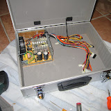
The following picture shows my initial setup for flying.


The picture was taken when I bought the MCP and the EFIS from CPFlight to flight with 767LD.

At that time I was aware that the hardware is not for 767 but for 737 but the 737 buttons are mapped in the 767 ones.
I am quite satisfied but I have to say that CPFlight system is not 100% bugs free; in particular it happens from time to time that the MCP turns black and non responsive during final approach phase and the HDG reset to 0.
This last bug is quite annoying because if in lateral mode, the HDG reset to 0 and the plane starts to run toward 360.


I use the biggest monitor with the main view of FSX.

I still fly with the traditional 2D view but I am trying to get used to the virtual cockpit that is much more useful especially for taxing and flight preparation.
The virtual cockpit is much more useful and realistic but with the 2D I have everyting available at a glance.
When my home cockpit will be ready, I guess I do not need the 2D anamore and I can safely switch to virtual cockpit


The second monitor contains secondary panels like pedestal, overhead, FMC, IVAP together with charts.

I do not use tools like IVAE, QuteScoop, FSNavigator and so on because I think the reduce the realism.


The joy is a Saitek X45.
X45 is not produced any more but is still a good product having the main stick with 2 axes and the throttle handle with an axis to control ailerons and the nose gear.

There are enough buttons to raise and lower the flaps, apply differential brakes, push to talk, main brakes and so on. In this way I can afford approaches and landings without the help of the keyboard.


Just a few words more about the picture upon.
The 767LD is at LIEE, both engines off, and I was testing the hardware from CPFlight. You can see a lot of cables in the left side that connect the MCP to the windows box and to the power, other cables connect the 2 parts of the joy together and the USB socket.

When I installed the MCP and the EFIS I was still stuck to a traditional way of simulating. I was really surprised of the improvements the hardware gave to the realism and I start thinking to build a kind of home cockpit to fly reducing the interaction with the keyboard and the mouse.

This was the start of my dream and a new hobby: build my prsonal version of an home cockpit.
I will talk you more about that in one of my next posts.


This post has been written by copy and paste from my home page.
The original content will be removed from my home page very soon.

Wednesday, February 20, 2008

VoloVirtuale

I was quite busy working during the past days.
I am still busy and now I am in Socorro NM on a mission to work even more.

Since a couple weeks I am moderator of a very famous italian forum for air simulation.
I hope you have time to visit the forum: VoloVirtuale It is the most clicked forum for simaviation in italy.


It is hard to believe how many options has a moderator. The forum seems much more complicated to me now. And it requires to me much more time: I have to read a lot of posts and think of each one against the forum policy.
It is a great honor for me to have been appointed to such a position. I have to thank all the VV staff for giving me this opportunity.
I hope to do a good there.

Wednesday, February 6, 2008

Creation of the blog

It is a long time I am thinking to create a blog. Today I had the chance to visit one of my friend's blog and decided to start.

In the past I was writing all my stuff into my home page, writing HTML code with the help of eclipse but I think a blog is more appropriate. So, as a starting point, I will move here what actually is in my home page.

My great passion is flying with the flight simulator and I have started building my home cockpit. Well it is not a replica of a real one because I do not have enough room available for that at the moment. The goal is to fly without keyboard and mouse. I am going to write here what I am doing, why and how.

This is the main purpose of this blog but I guess I could occasionally add comments about my free time and my second passion: snorkelling.